Simple Light detector circuit using transistor or Morning Alaram
You can imagine the birds chirping in morning for waking you up. A light detector sensor is same as birds it senses the lights and gives output buzzer sound and LED glow.
Simple LDR Circuit
We are going to make this circuit with some few components which is very easy and very smaller in size than using IC based circuit.
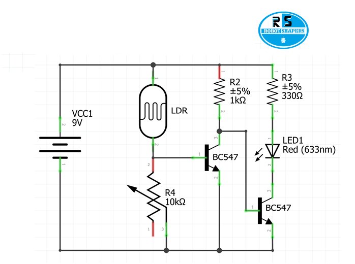
Circuit Diagram

Components required:
- 2 x BC547 NPN Transistors
- Small LDR
- 1 KΩ Resistor
- 10 KΩ Potentiometer
- White LED
- 330 Ω Resistor
- Connecting wires
- Power supply (9V Battery)
Working:
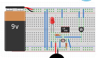
we have made light detection sensor using LM358 IC. But in order to make it more compact we will use basic components of electronics like transistors and resistors only.
we are using Darlington pair in which two transistors are used. We are using two transistors for proper output and sensivity of sensor.
we have connected a 10 Kohm variable resistor between the base of first transistor and ground and an LDR sensor between the base and Vcc. When there is a light hits the LDR it lowers its resistance.
This action will gives charge in collector side to drop to the ground .Second transistor in which collector side is connected to the LED’s ground pin and emitter is connected to the ground.
In second transistor again the charge at collector is dropped on the emitter side which is connected to the ground. This action completes the circuit for LED and it glows.
In order to make variable sensitivity the resistance on variable resistor can be changed. For higher sensivity the resistance should be high so that the voltage on the base of first transistor stays high and for lower sensitivity which means higher light intensity will be sensed, the resistance should be low.
Application:
- This can be used in morning alarm.
- It can also be used in burglar alarm.
- Automatic pass light in car .

 RobotShapers


