how to make 555 timer based touch switch project
Many times you may think of using touch panels instead of buttons in every electrical device like fan, lights, television etc. In this article again we are going to make one of 555 timer projects. 555 Bi-stable mode is going to be used here. As we’ve previously learn t that bi-stable mode of timer can give two states of high output and low output. We achieve these stated by adding two buttons in the circuit but her in this circuit we are going to use touch pins or panels and different combination of resistors in 555 bi-stable mode
 RobotShapers
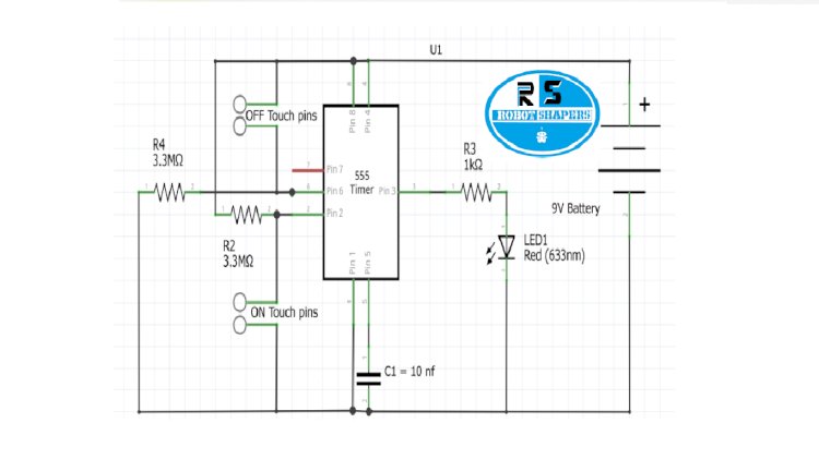
555 timer:
Pin 1. Ground: it is connected to the negative terminal of battery.
Pin 2. TRIGGER: Trigger pin is input pin or trigger pin if this pin is high the out put pin will always be high.
Pin 3. OUTPUT: This provides output voltage.
Pin 4. Reset: There is reset pin in this circuit this is connected to the Vcc as to auto-reset the function of IC.
Pin 5. Control Pin: This pin will be connected to the ground through a capacitor to avoid unwanted noise interference. This pin controls the output waveform width and also decides the level of thresh hold and triggering.
Pin 6. THRESHOLD: This pin decides the reset timing of the IC.
Pin 7. DISCHARGE: This pin toggles output from high to low when collector gets discharged.
Pin 8. Power or VCC: It is main supply pin of IC. It voltage ranges from 3.5 to 16 volts.
Working:
In above circuit we have used 333 Mega Ohm resistors. Between Pin 2 and ground pin on panel is connected and between Pin6 and Vcc pin off panel is connected. When two pins of on panel is touched the output gets high which turns the LED on and when off panel it touched the led gets off due to low output.
Component required:
- NE555 IC
- RESISTORS R4= 3 M Ohm
R2 = 3.3 M Ohm
R3 =1K
- CAPACITOR C1 = 10nf
- LED
- 9v battery
Pin diagram:

Circuit diagram:

In above circuit we have used 333 Mega Ohm resistors. Between Pin 2 and ground pin on panel is connected and between Pin6 and Vcc pin off panel is connected. When two pins of on panel is touched the output gets high which turns the LED on and when off panel it touched the led gets off due to low output.
Breadboard Diagram

Application:
- On/off switches
- Alert security Buzzer
- Light switch
- Door lock systems