16×2 LCD Display Module
An LCD is an electronic display module that uses liquid crystal to produce a visible image. The16×2 LCD display is a very basic module commonly used in DIYs. Itcis used to display data and the message and 16 Columns & 2 Rows.
 Arindam Deshmukh
16×2 LCD Display Module
We come across Liquid Crystal Display (LCD) displays everywhere around us. Computers, calculators, television sets, mobile phones, and digital watches use some kind of display to display the time.
These displays are mainly based on multi-segment light-emitting diodes. There are a lot of combinations of display available in the market like 8×1, 8×2, 10×2, 16×1, etc. but the 16×2 LCD is widely used. These LCD modules are low cost, and programmer-friendly, therefore, is used in various DIY circuits, devices, and embedded projects.

In LCD 16×2, the term LCD stands for Liquid Crystal Display that uses a plane panel display technology, used in screens of computer monitors & TVs, smartphones, tablets, mobile devices, etc. Both the displays like LCD & CRTs look the same but their operation is different. Instead of electrons diffraction at a glass display, a liquid crystal display has a backlight that provides light to each pixel that is arranged in a rectangular network.
Every pixel includes a blue, red, green sub-pixel that can be switched ON/OFF. Once all these pixels are deactivated, then it will appear black and when all the sub-pixels are activated then it will appear white. By changing the levels of each light, different color combinations are achievable.
16×2 LCD is one kind of electronic device used to display the message and data. The term LCD full form is Liquid Crystal Display. The display is named 16×2 LCD because it has 16 Columns and 2 Rows. As the name suggests, it includes 16 Columns & 2 Rows so it can display 32 characters (16×2=32) in total & every character will be made with 5×8 (40) Pixel Dots. So the total pixels within this LCD can be calculated as 32 x 40 otherwise 1280 pixels.
16×2 LCD Display Module Pin Diagram
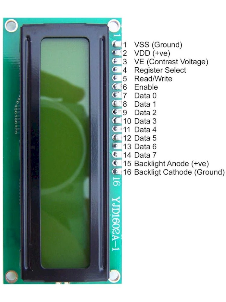
16X2 LCD Pin Configuration
|
Pin Number |
Pin Name |
Description |
|
1 |
Vss (Ground) |
VSS pin connected to microcontroller ground |
|
2 |
Vdd (+5 Volt) |
VDD pin connected to microcontroller + 5V power supply |
|
3 |
VE (Contrast V) |
Adjusts the contrast of the LCD display. It is Connected to a variable POT that can provide 0-5V power supply. Connect it to the ground to get maximum contrast. |
|
4 |
RS (Register Select) |
Toggles between Command/Data Register. Connect a microcontroller data pin and obtains either 0 or 1(0 = data mode, and 1 = command mode). |
|
5 |
RW (Read/Write) |
Used to read or write data. Normally grounded to write data to LCD |
|
6 |
E (Enable) |
This pin should be held high to execute the Read/Write process, and it is connected to the microcontroller data pin & constantly held high. |
|
7 |
D0 (Data Pin 0) |
These 8 Pins are used to sending commands or data to the LCD. These pins are connected in two-wire modes like 4-wire mode and 8-wire mode. In 4-wire mode, only four pins are connected to the microcontroller data pin 0 to 3. And in 8-wire mode, 8-pins are connected to microcontroller data pin 0 to 7. |
|
8 |
D1 (Data Pin 1) |
|
|
9 |
D2 (Data Pin 2) |
|
|
10 |
D3 (Data Pin 3) |
|
|
11 |
D4 (Data Pin 4) |
|
|
12 |
D5 (Data Pin 5) |
|
|
13 |
D6 (Data Pin 6) |
|
|
14 |
D7 (Data Pin 7) |
|
|
15 |
LED + (+5V) |
This is the positive terminal of the backlight LED of the display. It’s connected to +5V to turn on the backlight LED. |
|
16 |
LED – (Ground) |
This is the negative terminal of the backlight LED of the display. It’s connected to the ground to turn on the backlight LED. |
16X2 LCD Specification
|
Parameter |
Value |
|
Operating Voltage |
4.7V-5.3V |
|
Operating Current |
1mA with no backlight |
|
Controller |
HD47780 |
|
Number of Columns |
16 each row, total 16 x2 = 32 columns |
|
Number of rows |
2 |
|
Every character pixel box |
5×8 pixel |
|
Number of Character |
32 |
|
Character font-size |
0.125″W x 0.200″H |
|
Work Modes |
4-bit & 8-bit |
|
Backlight LED color |
Blue or Green |
|
Number of Pins |
16 |
|
Module PCB Size |
80 x 36 x 10 (LxWxH) mm. |
|
Display Bezel |
72 x 25mm (2.8 x 1″) |
- It includes two rows where each row can produce 16-characters.
- The alphanumeric LCDs alphabets & numbers
- It displays a few custom generated characters
16×2 LCD Commands
The commands of LCD 16X2 include the following.
- For Hex Code-01, the LCD command will be the clear LCD screen
- For Hex Code-02, the LCD command will be returning home
- For Hex Code-04, the LCD command will be decrement cursor
- For Hex Code-06, the LCD command will be Increment cursor
- For Hex Code-05, the LCD command will be Shift display right
- For Hex Code-07, the LCD command will be Shift display left
- For Hex Code-08, the LCD command will be Display off, cursor off
- For Hex Code-0A, the LCD command will be cursor on and display off
- For Hex Code-0C, the LCD command will be cursor off, display on
- For Hex Code-0E, the LCD command will be cursor blinking, Display on
- For Hex Code-0F, the LCD command will be cursor blinking, Display on
- For Hex Code-10, the LCD command will be Shift cursor position to left
- For Hex Code-14, the LCD command will be Shift cursor position to the right
- For Hex Code-18, the LCD command will be Shift the entire display to the left
- For Hex Code-1C, the LCD command will be Shift the entire display to the right
- For Hex Code-80, the LCD command will be Force cursor to the beginning ( 1st line)
- For Hex Code-C0, the LCD command will be Force cursor to the beginning ( 2nd line)
- For Hex Code-38, the LCD command will be 2 lines and 5×7 matrix
16X2 LCD Working Principle
The basic working principle of LCD is passing the light from layer to layer through modules. These modules will vibrate & line up their position on 90o that permits the polarized sheet to allow the light to pass through it.
These molecules are accountable for viewing the data on every pixel. Every pixel utilizes the method of absorbing light to illustrate the digit. To display the value, the position of molecules must be changed to the angle of light.
So this light deflection will make the human eye notice the data that will be the ingredient wherever the light gets absorbed. Here, this data will supply to the molecules & will be there till they get changed
At present, LCDs are used frequently in digital watches, computers, etc. In screen industries, LCDs have replaced the CRTs (Cathode Ray Tubes) because these displays use more power and are heavier & larger.
The displays of LCDs are thinner as compared to CRTs. As compared to LED screens, LCD has less power consumption because it functions on the fundamental principle of blocking light instead of dissipating.
Registers of LCD
A 16×2 LCD has two registers like data register and command register. The RS (register select) is mainly used to change from one register to another. When the register set is ‘0’, then it is known as command register. Similarly, when the register set is ‘1’, then it is known as data register.
Command Register
The main function of the command register is to store the instructions of command which are given to the display. So that predefined tasks can be performed such as clearing the display, initializing, set the cursor place, and display control. Here commands processing can occur within the register.
Data Register
The main function of the data register is to store the information which is to be exhibited on the LCD screen. Here, the ASCII value of the character is the information which is to be exhibited on the screen of LCD. Whenever we send the information to LCD, it transmits to the data register, and then the process will be starting there. When register set = 1, then the data register will be selected.
Now, let us turn back our LCD:
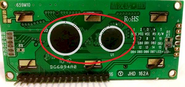
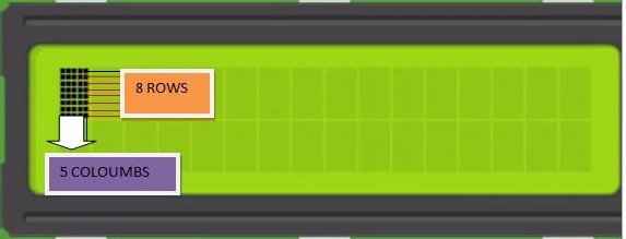
These black circles consist of an interface IC and its associated components help us to use this LCD with the MCU. Because our LCD is a 16*2 Dot matrix LCD and so it will have (16*2=32) 32 characters in total and each character will be made of 5*8 Pixel Dots. A Single character with all its Pixels enabled is shown :-

So Now, we know that each character has (5*8=40) 40 Pixels and for 32 Characters we will have (32*40) 1280 Pixels. Further, the LCD should also be instructed about the Position of the Pixels.
To handle everything with the help of MCU is quite difficult, hence an Interface IC like HD44780 is used, which is mounted on LCD Module itself. The function of this IC is to get the Commands and Data from the MCU and process them to display meaningful information onto our LCD Screen.
The different type of mode and options available in our LCD, controlled by our Control Pins.
4-bit and 8-bit Mode of LCD:
The LCD can work in two different modes, namely the 4-bit mode and the 8-bit mode. In 4 bit mode we send the data nibble by nibble, first upper nibble and then lower nibble [a nibble is a group of four bits]. So the lower four bits (D0-D3) of a byte form the lower nibble while the upper four bits (D4-D7) of a byte form the higher nibble. This enables us to send 8 bit data.
Whereas in 8 bit mode we can send the 8-bit data directly in one stroke since we use all the 8 data lines.
8-bit mode is faster and flawless than 4-bit mode. But the major drawback is that it needs 8 data lines connected to the microcontroller. This will make us run out of I/O pins on our MCU, so 4-bit mode is widely used. No control pins are used to set these modes. It's just the way of programming that change.
Read and Write Mode of LCD:
The LCD itself consists of an Interface IC. The MCU can either read or write to this interface IC. Since reading will make it more complex and such scenarios are very rare. Information like position of cursor, status completion interrupts etc. can be read if required.
The Interface IC present in most of the LCD is HD44780U, in order to program our LCD we should learn the complete datasheet of the IC.
Displaying Custom Characters on 16X2 LCD
Generating custom characters on LCD is not very hard. It requires knowledge about the custom-generated random access memory (CG-RAM) of the LCD and the LCD chip controller. Most LCDs contain a Hitachi HD4478 controller.
CG-RAM is the main component in making custom characters. It stores the custom characters once declared in the code. CG-RAM size is 64 bytes providing the option of creating eight characters at a time. Each character is eight bytes in size.
CG-RAM address starts from 0x40 (Hexadecimal) or 64 in decimal. We can generate custom characters at these addresses. Once we generate our characters at these addresses, we can print them by just sending commands to the LCD. Character addresses and printing commands are :-
|
CG-RAM Characters |
CG-RAM Address (Hexadecimal) |
Commands to Display Generated Characters |
|
1ST Character |
0x40 |
0 |
|
2ND Character |
0x48 |
1 |
|
3RD Character |
0x56 |
2 |
|
4TH Character |
0x64 |
3 |
|
5TH Character |
0x72 |
4 |
|
6TH Character |
0x80 |
5 |
|
7TH Character |
0x88 |
6 |
|
8TH Character |
0x96 |
7 |
The first character is generated at addresses 0x40 to 0x47 and is printed on LCD by just sending a command 0.
The second character is generated at addresses 0x48 to 0x55 and is printed by sending a command 1.
How to Generate Custom Characters in CG-RAM
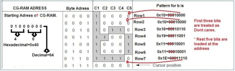
In LCD displays, each character is in a 5×8 matrix. Where 5 is the number of columns and 8 is the number of rows.
Here is a simple example of how to create the letter ‘b’ in CG-RAM.
The Array for generating ‘b’ is char b[7]={0x10,0x10,0x16,0x19,0x11,0x11,0x1E}; That is,
-
Send the address where you want to create a character.
-
Now create your character at this address. Send the ‘b’ character array values defined above one by one to the data register of the LCD.
-
To print the generated character at 0x40. Send command 0 to the command register of LCD. The table below would explain :-
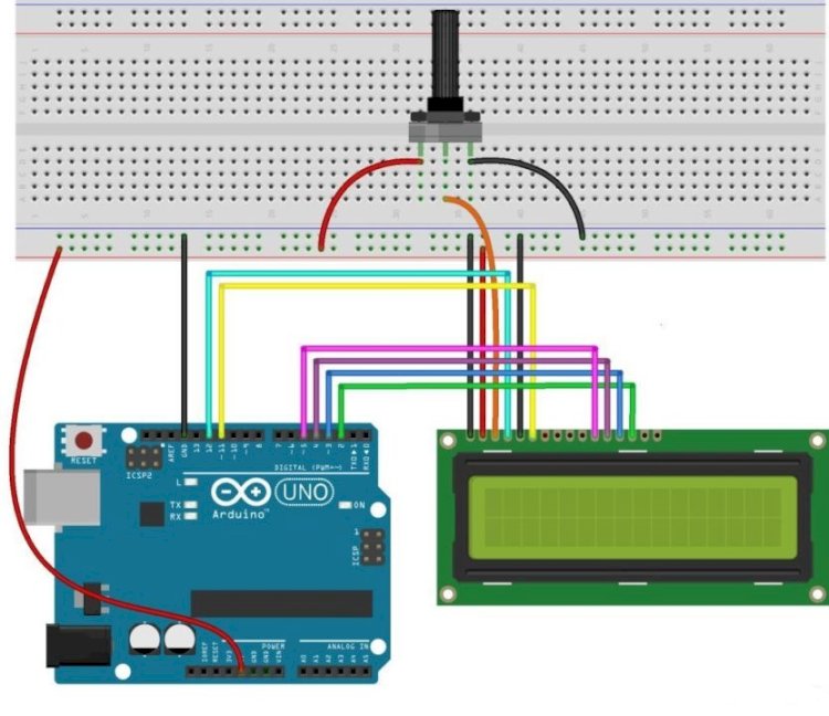
Interfacing LCD 16×2 with Arduino
A library like LiquidCrystal permits you to manage the displays that are well-matched through the driver like Hitachi HD44780 driver. Here, the following example circuit displays “Hello World!” on the LCD & displays the time in sec once the Arduino board was reset.
The 16×2 display includes a parallel interface which means that the microcontroller used in this has to control different interface pins immediately to control the LCD. The interface includes mainly these pins like RS (Register Select) pin, Read/Write pin, Enable Pin, Data pins from D0 to D7, display contrast pin, LED backlight pins, power supply pins.
The display controlling process mainly involves placing the data to form the picture of what you desire to show into the data registers, after that placing instructions within the instruction register. A library like LiquidCrystal will simplify this for you so you don’t require identifying the instructions in low-level.
The controlling of LCDs compatible with Hitachi can be done using two modes like 4-bit/8-bit. Here, the 4-bit mode needs 7 I/O pins using the Arduino board, whereas the 8-bit mode needs 11 pins. To display the text on the LCD, the 4-bit mode is used. The following example will explain how to control an LCD using 4-bit mode.
The required components of interfacing 16X2 LCD with Arduino include the following.
-
LCD Screen
-
Hook-up Wires
-
Pin headers for soldering the display pins of LCD
-
Resistor – 220 ohm
-
Potentiometer – 10k ohm