how to make 555 timer based Mosquito repellant project
In Previous articles we have discussed three modes of 555 timer IC, these are a-stable, bi-stable & mono-stable and also we have made a PWM circuit. In this article also we will make a PWM circuit but for different application. Here we are making a mosquito repellent circuit. This circuit is very much similar to the PWM motor control circuit but here we will need different resistor and capacitor combination to make a higher frequency and also we are controlling the sound frequency so the resistors value will be taken high and capacitors accordingly. The frequency should be high for giving an annoying sound for mosquito.
 RobotShapers
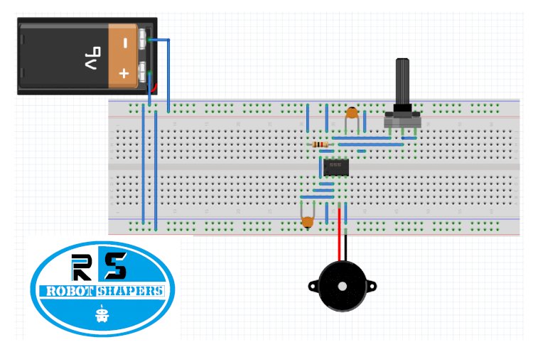
555 timer:
Pin 1. Ground: it is connected to the negative terminal of battery.
Pin 2. TRIGGER: Trigger pin is input pin or trigger pin if this pin is high the out put pin will always be high.
Pin 3. OUTPUT: This provides output voltage.
Pin 4. Reset: There is reset pin in this circuit this is connected to the Vcc as to auto-reset the function of IC.
Pin 5. Control Pin: This pin will be connected to the ground through a capacitor to avoid unwanted noise interference. This pin controls the output waveform width and also decides the level of thresh hold and triggering.
Pin 6. THRESHOLD: This pin decides the reset timing of the IC.
Pin 7. DISCHARGE: This pin toggles output from high to low when collector gets discharged.
Pin 8. Power or VCC: It is main supply pin of IC. It voltage ranges from 3.5 to 16 volts.
What is Pulse width Modulation:
This method of signaling is used to control analog type devices with digital form of output. In this method we use a pulsating output frequency to control device motion or it’s outcome strength. Like we can control motor speed or create vibrating or increase or decrease light intensity etc. It is like an on and off sequence of power supply for running a device like motor in controlled manner. We generally use voltage variation for controlling motor speed but this method reduces it torque with voltage. In PWM method we can achieve different speeds with same torque or power. For understanding PWM better we should know about duty cycle also.
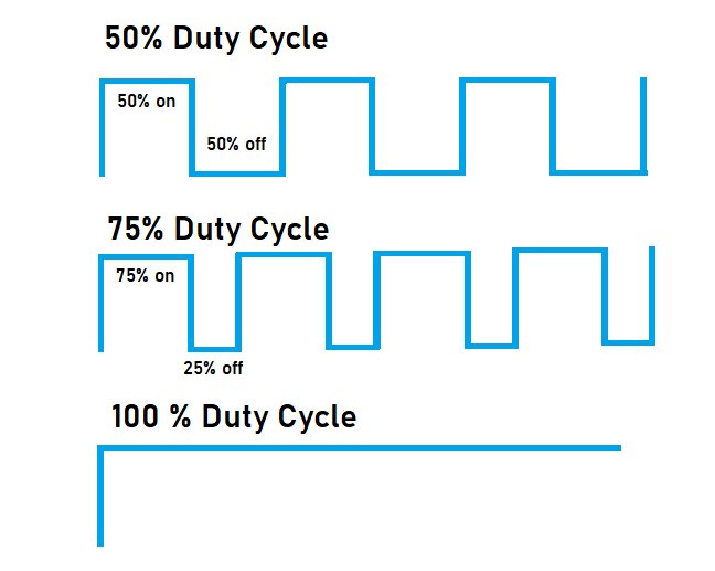
Duty cycle:
Duty cycle is the time interval of pulse when the output of circuit is high or it is giving output voltage. For example the graph given below is showing 50% of duty cycle and below this graph two more graphs are showing 75% and 100 % duty cycle. This percent of duty cycle results in output speed of motor. If motor is required to run on full speed it should be given 100% duty cycle or it is required to run on half speed it will be given 50% duty cycle.
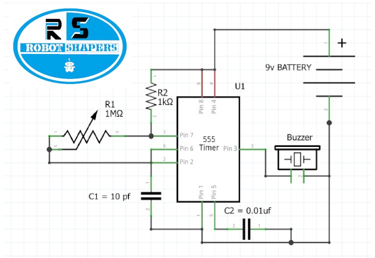
Circuit diagram:
circuit diagram
Breadboard diagram
Component required:
- NE555 IC
- RESISTORS R2= 1K
- CAPACITOR C1 = 100 nf
- Variable Resistor VR1 = 100 K Ohm
- LED
- 9v batterywith cap
Working:
In above circuit we have used 555 timer A-stable mode here we are using pulsating output in a different manner as we know the pulse on and off time depends on the resistors and capacitors we are using, one component of it has to be variable. Like in previous article capacitor and one resistor R2 is fixed and second resistor is variable, also a capacitor is added in pin 5 .This variable resistor will control the duty cycle in very high frequency for which its value is taken high (1Mega Ohm) .Here we are using a buzzer instead of motor as we need sound frequency. Similarly as we increase the resistance between pin 6 and pin 7 the speed of motor gets increased due to increment in duty cycle and decreases when resistance is reduced.
Application:
- Mosquito repellant
- Volume controller
- Volume meter of radio or music system