Arduino DC Voltmeter
"Unleashing the Power of Arduino: Enter the Realm of DC Voltmeter with Robotshapers" takes you on an electrifying journey through voltage measurement. Discover the artistry of connecting voltmeters in parallel, while digital voltmeters offer unmatched accuracy. Explore the Arduino board's versatility and the magic of the 16x2 LCD Display. Witness the countless applications of the DC Voltmeter in power systems, automotive diagnostics, renewable energy, and more. Experience the Arduino's simplicity and create interactive blueprints and prototypes. Dive into the world of pins and their unique functions. Join Robotshapers as they empower you to measure, monitor, and master voltage with Arduino.
 robotshapers1
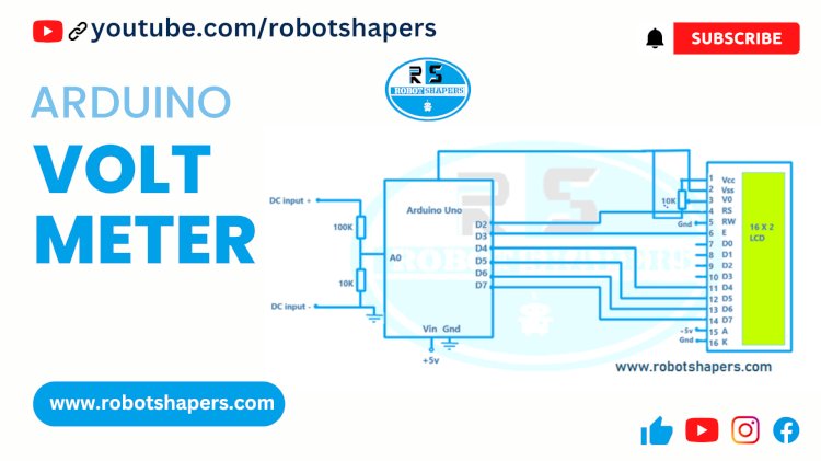
Voltmeter is a device used to measure voltage. It works by connecting a voltmeter in parallel to the component or circuit under test. A voltmeter has a display unit and an internal circuit that measures voltage across the circuit. When using electricity, the voltmeter measures the difference between voltages and displays the reading in volts. Voltmeters can be analog or digital, digital voltmeters provide greater accuracy. They are essential tools in electronics, electrical engineering and troubleshooting and allow users to monitor and analyze voltage levels in circuits, batteries and electrical equipment, electrical and other electronic equipment.
Component Details:
- Arduino Uno
- 16X 2 LCD
- 10 K resistors (2 nos)
- 100 K resistor
- 10 k variable resistor
- 5V DC power supply
Arduino microcontroller details:
Arduino is an open source electronics development kit. Arduino boards come in many different forms, including microcontrollers, digital and analog input/output pins, and interfaces for connecting sensors, actuators, and other electronic devices. It can be programmed using the Arduino IDE (Integrated Development Environment), a user-friendly software. Arduino is popular for its simplicity, versatility, and many uses, from hobby projects to industrial automation. It allows users to create interactive blueprints, prototypes and IoT devices by writing code and posting it on the development board, and provides access to two beginners and hobbyists.
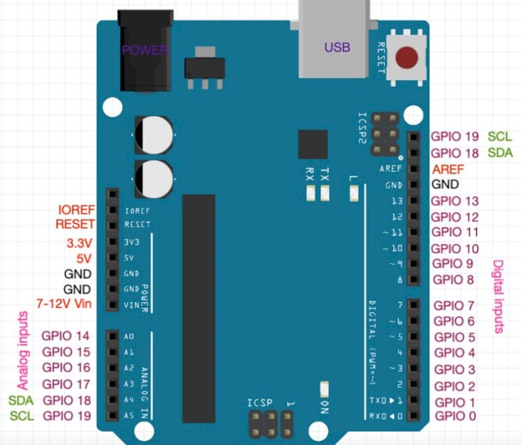
- The Arduino board has different pins that can be divided into three types: pins, analog pins and special function pins.
A brief summary of the pin details for most Arduino boards: - Digital Pin: The pin is used for digital input or output functions. is usually D0, D1, D2, etc. labeled as. This can be configured as an input or an output.
Most Arduino boards have 14 to 20 pins numbered D0 to D13 (sometimes more). - Analog Pin:analog pin is used for analog input function to read voltage value. Usually A0, A1, A2, etc. labeled as. can also be used as a digital pin. The number of analog pins depends on the Arduino board model (usually 6 or more).
- Special Function Pins: These pins are used for special purposes such as power supply, operation and communication. Most special function pins of arduino include:
- TX, RX: Pins for serial communication (UART).
- SDA, SCL: Pins for I2C communication (available on some boards).
- MOSI, MISO, SCK: Pins for SPI communication.
- GND: Ground (0V) reference.
- 5V: +5V power supply pin.
- 3.3V: +3.3V power supply pin (available on some boards).
- VIN: Input voltage pin (usually used for power board).
16 X 2 LCD:
16x2 LCD (Liquid Crystal Display) is a kind of alphanumeric display module. It contains 16 lines and 2 lines of characters and can display up to 32 characters at a time. The location of each character usually consists of a 5x8 pixel matrix. The LCD module has a control chip that manages the operation and communication with the microcontroller. It can interface with various microcontrollers and Arduino boards. 16x2 LCDs are widely used in electronic schemes and applications that require instructional knowledge such as digital clocks, thermometers, mechanical sensors and data loggers.
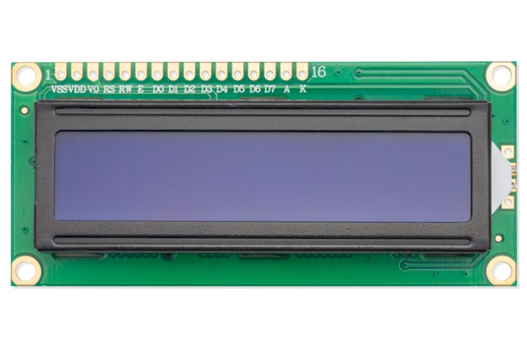
16x2 LCD (Liquid Crystal Display) usually has 16 pins and is used to connect to microcontroller or other devices.
Here is a brief description of the standard 16x2 LCD pin structure details:
- VSS (Ground): Connects to ground or the system uses 0V.
- VDD (+5V): Connect to positive power supply voltage (usually +5V).
- V0 (contrast): Connect a variable or potentiometer to adjust the contrast of the screen.
- RS (select option): Select LCD data register (RS=0) or command register (RS=1).
- R/W (read/write): Controls the direction of data transfer.
- R/W=0 means write mode, R/W=1 means read mode (usually grounded for write only).
- E (Enable): Activate the LCD to read or write data. 7-14. D0-D7 (Data Line): These 8 pins carry data (D0-D7) when transferring data to or from the LCD.
- A (Anode) or LED + (Backlight Positive Voltage): Connect to the positive terminal of the Backlight LED (if applicable).
- K (cathode) or LED- (background): Connect to the negative terminal of the backlight lamp (if applicable).
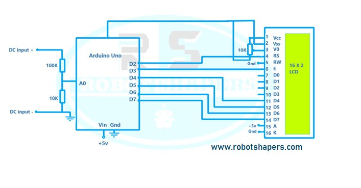
Circuit diagram:
Code:
#include
LiquidCrystal lcd(2, 3, 4, 5, 6, 7);

int analogInput=A0;
float vout;
float vin;

float R1 = 100000.0;
float R2 = 10000.0;
int value;
int value2;

void setup() {

  pinMode(analogInput, INPUT);
  lcd.begin(16, 2);
  lcd.setCursor(2, 0);
  lcd.print("DC VOLTMETER");
  delay(1500);
  lcd.clear();

}
void loop() {

lcd.setCursor(2,0);
  lcd.print("Voltage:");
   lcd.print(vin);

  value = analogRead(analogInput);
  vout = (value * 5) / 1023.0;
  vin = vout / (R2 / (R1 + R2));

  if (vin < 0.09)
  {
    vin = 0.0;
  }
}
Applications:
The DC Voltmeter has many applications in different industrial and commercial applications. Here are some important applications:
- Electrical Measurement: DC voltmeters are often used in electrical measurement to measure and verify voltage levels in circuits, electrical equipment and equipment.
- Power system: DC voltmeters play an important role in monitoring and monitoring power. They help technicians and engineers measure the voltage in batteries, solar panels, and other energy stores.
- Automotive industry: DC voltmeters are essential for diagnosing and repairing electrical problems in automobiles. They are used to measure voltage in car batteries, alternators and other electrical equipment.
- Electrical Applications: DC voltmeters are used to monitor voltage levels and provide maximum power in renewable energy systems such as wind turbines and solar installations, yes.
- Battery Test: Battery tester uses a DC voltmeter to measure the voltage and health of the battery to ensure proper functioning and determine if it needs to be replaced or reimbursed.
- Industrial Control: DC voltmeters are used in industrial control systems to monitor and control voltage levels in machinery, equipment and electrical distribution systems.
- Communications: DC voltmeters are used in the communications industry to measure and monitor voltage levels in communications equipment, power supplies, and battery backups.
- Research and Development: DC voltmeters are an essential tool in scientific laboratories for measuring and measuring voltage in experimental setups, prototypes, and actually researched devices.
- Electrical Safety: DC voltmeters are used in electrical safety inspections and monitoring to ensure voltage stability and compliance with safety standards.
- Education and training: DC voltmeters are widely used in schools and education to teach students the concepts of electrical measurement, circuits and electricity.
Best projects in Bhilia, Chhattisgarh, India. Contact: 7067150002