How to make music operated LED chaser ckt - VU meter using LM3915 - LED disco
Description: Every one of us loves to listen music and when it comes to party we love it with lights. We are going to make one of the dancing light which will dance with the music. Actually we are making a VU or we can say sound level meter in our circuit. This thing is very much fun to make because it looks beautiful when played in the dark room.
 RobotShapers
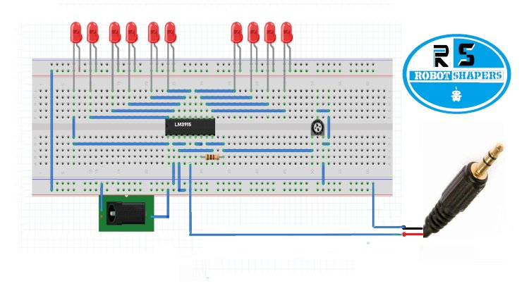
LM3915
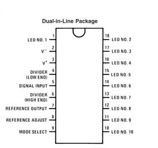
LM3915-pinout
PIN 1,10 – 18 – 10 LEDs
PIN 2 – Ground
PIN 3 – VCC(around12v as we want to drive 12 v led)
PIN 4 – Low-level voltage divider
PIN 5 – Audio signal input
PIN 6 – High-level voltage divider
PIN 7 – Reference for led limit
PIN 8 – Adjust pin for reference
PIN 9 – Mode selection pin
Circuit diagram:

LM3915 Vu meter circuit diagram

LM3915 Breadboard diagram
Working:
In above circuit we have used two transistors but it can be done with one transistor also in case of water and if we want moisture thing to be sensed we can use more than two transistors. A transistor has 3 pins collector base and emitter. When any signal voltage is given to the base or we can say base voltage gets high the charge on the collector drops toward emitter side. Here the transistor connects the ground pin of the buzzer and led to the ground voltage terminal when signal is given to the base. Here signal to the second transistor is coming from the emitter side of first transistor. The drop terminals are two pins or we can use open wire one of which is connected to the base of transistor and other with main +ve voltage when a drop of water touches this two pins together the main voltage connects with base of first transistor a resistor of 1k is connected to avoid voltage increment damage. So this action makes first transistor drops the voltage to the base of second transistor and second transistor then connects the Buzzer and LED to the ground which makes the light glow and buzzer beep.
Component required:
- Lm3915 IC
- Power LED (x10)
- R1 =1k resistor
- Variable resistor VR2 =10k
- jumper wire
- LED
- 3mm male audio jack
- 12 Volt DC adapter or SMPS
Working:
In the circuit diagram you can see we have used power LED that runs on 12volt but if you are using normal 5mm or 3mm LED which runs on 3v, you can add 1k resistor before connecting LEDs to the main voltage and then even 9v battery can also be used for this project.
We have added +12v on Vcc PIN 3 and mode selection pin 9. Pin 9 is high with main supply because it gives a bar mode output in which along with higher level led the rest lower level also glows. In another dot mode pin 9 is kept low which allows only the uppermost led of level. A variable resistor is also added in this circuit to make level adjustments. Pin 2 and pin4 will be grounded and pin 5 will be connected with sound input.
Application:
- Sound level testing
- Dancing LED
- Decoration LED
- Vibration meter
For video link: