RF based helmet detection system
Introducing Radio Frequency Helmet Detection System for Vehicle Safety by Robotshapers! At Robotshapers, we prioritize road safety and understand the importance of wearing helmets while riding. Introducing our innovative solution, a microcontroller-based system with radio frequency communication. When a helmet is worn, it sends a signal to the microcontroller, ensuring the ignition remains active. We've also incorporated a relay circuit to be connected in parallel to the connector or contact, ensuring the circuit is closed only when the helmet is worn. With RF technology, the system guarantees reliable communication between the helmet and the vehicle. Stay safe with Robotshapers' cutting-edge helmet detection system. Visit robotshapers.com for more information.
 robotshapers1
It is well known that road accidents are always dangerous if safety rules are not followed. One of the basic rules is to wear a helmet. But some people forget to wear it while riding. A device that can stop the ignition of the vehicle when the helmet is not worn should be purchased.
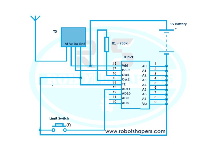
In our project, we are making a microcontroller system with radio frequency communication that will give a signal to the microcontroller when a helmet is worn, and there is also a relay circuit, which must be connected in parallel to the connector or the contact must be closed.
Components required:
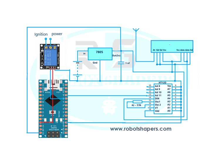
- Arduino Nano
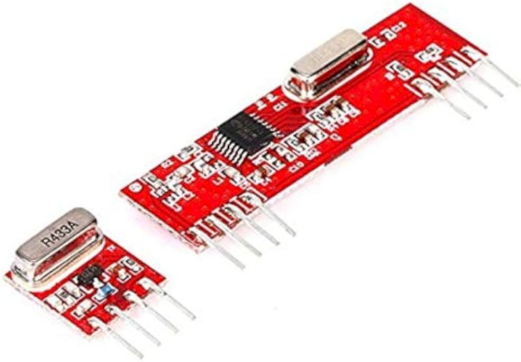
- RF- module
- HT12D IC
- HT12E IC
- 16x2 LCD
- 12V DC battery
- 9V DC battery
- 750 K resistor
- 33 K resistor
- 10 K resistor
- 10K variable resistor
- 1k resistor
- Single channel relay
- 7805 voltage regulator
- Limit switch
- Helmet
RF (Radio Frequency) Fundamentals:
RF Module: It is the main module that controls RF signal transmission and reception. It usually includes components such as RF transceivers, amplifiers, modulator/demodulators, and other circuitry necessary for RF communication.
Antenna: An important part of the radio frequency module used to send and receive radio frequency signals wirelessly. The antenna is connected to the radio frequency module to facilitate the transmission and reception of the signal.
Microcontroller: This device is responsible for the control of the radio frequency module.
It can be a microcontroller or microprocessor that supports communication protocols (such as SPI, UART) to interact with the RF module. The microcontroller communicates with the RF module to send and receive data wirelessly.
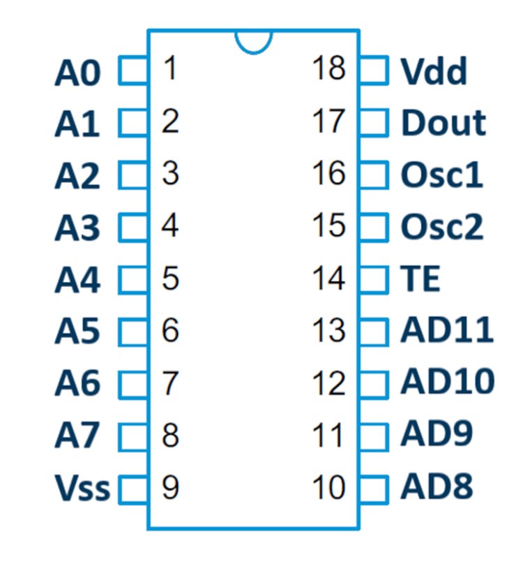
HT12D IC:
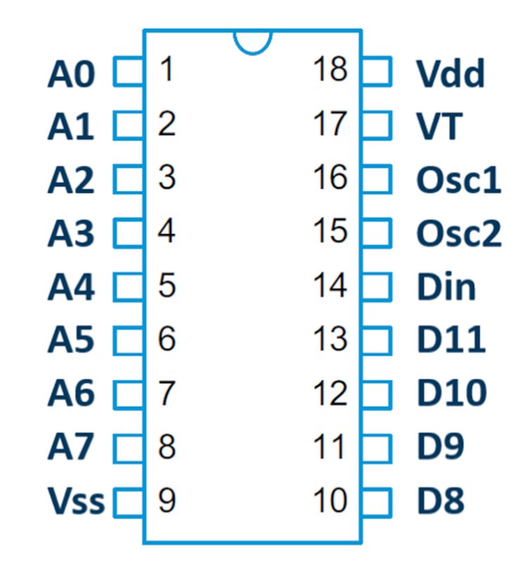
The HT12D is a popular Integrated Circuit (IC) with 212 series remote control decoder ICs manufactured by Holtek Semiconductor. It is often used in remote control systems to determine the signal transmitted by the encoder IC (such as HT12E).
Here are some details about HT12D IC:
- Function: HT12D is an 8-bit IC decoder used to receive and decode data sent by HT12E encoder IC. By converting serial data to parallel data, it ensures that the original data sent is received.
- operating voltage: The operating voltage range of the HT12D is 2. 4V to 12V. It has a wide range of operating voltages and allows it to be used with a variety of electrical equipment.
- Data Converter: This IC uses 2/12 data address decoder. It takes a 12-bit serial data stream and compares it to the local address set on its address pin. If the received address matches the local address, the corresponding data is output.
- Address pins: HT12D has 8 address pins (A0-A7) to set the address. These pins determine the specific address of the IC and are required to match the set address code with the HT12E encoder for successful data transfer.
- Data Pins: The IC has four data output pins (D8-D11) that provide data output. These pins output serial data corresponding to the serial data received from the HT12E encoder.
- Power Down Mode: The HT12D has a power down mode that helps save power when the IC is not used.
When the TE pin (pin 14) is grounded, the IC draws low current and enters a low state. - Application: HT12D IC is used for various remote controls such as wireless security systems, remote keyless entry systems, toys remote control and home automation systems.
It is important to note that the information presented here is based on the general instructions of the HT12D IC. For detailed information on electrical specifications, pin configurations, and other specific information, it is recommended that you consult the manufacturer's data or information for accurate and most up-to-date information.
HT12E IC:
HT12E is an integrated circuit (IC) widely used in 212 series remote control encoder IC manufactured by Holtek Semiconductor. It is often used with HT12D decoder IC to realize the wireless remote control system. Here are some details about HT12E IC:
- Function: HT12E is an 8-bit encoder IC that generates serial data for transmission by remote control. It takes data as input in parallel and converts it to serial format for transmission.
- working voltage: HT12E's working voltage range is 2. 4V to 12V. This wide operating voltage provides flexibility in power supply.
Address Pins: The IC has 8 address pins (A0-A7) that allow you to create a unique address. These pins determine that the HT12D decoder needs a matching field to receive complete data. - Data Pins: The HT12E has four data input pins (D8-D11) that accept parallel data input.These pins receive small data that needs to be sent wirelessly.
- Control Pins: The IC contains three control pins: TE (Transfer Enable), the time transfer pin that initiates data transfer; D8 (Data Migration) that activates changes when pulled down; VT (valid), output pin to indicate successful transfer.
- Oscillator: The HT12E has an internal oscillator circuit that generates the clock signal required for data encoding. The oscillator frequency is usually determined by an external resistor and a capacitor connected to pins OSC1 and OSC2.
- Application: The HT12E IC is mainly used in remote control applications such as wireless security systems, remote keyless entry systems, garage doors and home automation systems.
It is important to note that the information shown here is based on the general characteristics of the HT12E IC. For detailed information on electrical specifications, pin configurations and other special information, it is recommended to consult the manufacturer's data or information for correct information and update.
Circuit diagram for transmitter:
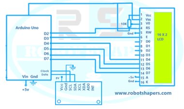
Circuit diagram for reciever:
Code:
#define RF 3// RF signal pin
#define IG 6// relay pin which connects the ignition
#include
LiquidCrystal lcd(A0,A1,A2,A3,A4,A5);

  void setup()
  {
  Serial.begin(9600);
  lcd.begin(16,2);
  pinMode(RF,INPUT);
    pinMode(IG,OUTPUT);
    lcd.setCursor(0,0);
   lcd.print("ROBOTSHAPERS");
   delay(1500);
   lcd.setCursor(0,1);
   lcd.print("HELMET DETECTOR");
   delay(1500);
   lcd.clear();
  }
void loop()
 {
  if( digitalRead(RF)==LOW)
  {
    digitalWrite(IG,LOW);
  lcd.setCursor(0,0);
   lcd.print("VEHICLE - ON ");
    lcd.setCursor(0,1);
   lcd.print("WELCOME    ");
  }
  if( digitalRead(RF)==HIGH)
  {
    digitalWrite(IG,HIGH);
  lcd.setCursor(0,0);
   lcd.print("VEHICLE - OFF");
    lcd.setCursor(0,1);
   lcd.print("WEAR HELMET");
   }
 }
Advantages:
- This system provides precaution for safety before accident.
- This system creates a habit of wearing helmet during ride which is good for safety.
- The system works on vehicle battery.
Best proejcts in Bhilia, Chhattisgarh, India. Contact: 7067150002