LM386 Audio Amplifier - basic electronics projects
In our daily life we spent lots of money in purchasing music system. But in this article we are going to learn about making it spending some coins in our pocket. Audio amplifier circuit is used in every audio device like earphones, mic, speakers etc.
 RobotShapers
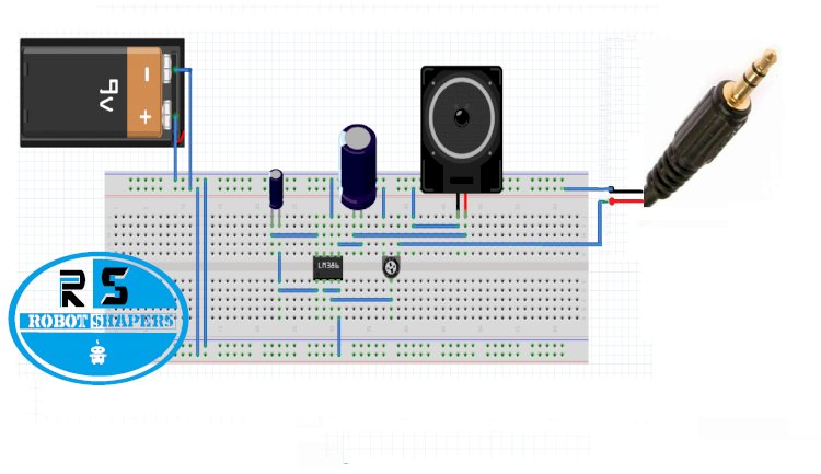
LM386 :
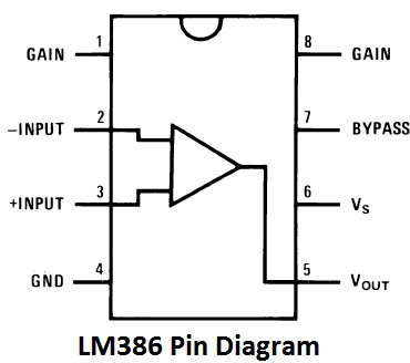
Fig.1.1
Pin 1 and Pin 8 Gain: These pins are gain terminal if we put a resistor between these pins the gain voltage is controlled and if a capaictor is placed the high voltage is gained.
Pin 2 and Pin 3 Input Pins: These pins are input for sound input . Pin 3 is input and pin 2 will be grounded and if pin 3 is taken as input then pin 2 will be grounded.
Pin 4: Ground
Pin 5: Output
Pin 6 Vcc: Around 6-12 Volt
Pin 7 Bypass : This pin is used for better stability of sound

Fig.1.2 circuit diagram
Working:
In above circuit we have used two transistors but it can be done with one transistor also in case of water and if we want moisture thing to be sensed we can use more than two transistors. A transistor has 3 pins collector base and emitter. When any signal voltage is given to the base or we can say base voltage gets high the charge on the collector drops toward emitter side. Here the transistor connects the ground pin of the buzzer and led to the ground voltage terminal when signal is given to the base. Here signal to the second transistor is coming from the emitter side of first transistor. The drop terminals are two pins or we can use open wire one of which is connected to the base of transistor and other with main +ve voltage when a drop of water touches this two pins together the main voltage connects with base of first transistor a resistor of 1k is connected to avoid voltage increment damage. So this action makes first transistor drops the voltage to the base of second transistor and second transistor then connects the Buzzer and LED to the ground which makes the light glow and buzzer beep.
Component required:
- Lm386 IC
- Speaker 8 watts
- Variable resistor VR1 =10k
- jumper wire
- 3mm male audio jack
- 9Volt Battery with Cap
- Capacitors
C1 = 100 uf
C2 = 10 uf
Working:
In the circuit diagram you can see Pin 7 is left open as we are having a clear sound. But when we use little high wattage speakers then for controlling the bass vibration we will use capacitors with this Pin. Before connecting the speaker to the output we have added a capacitors this gives a clear sound and avoid extra bass vibration in speaker. A 10 k variable is added with input pin. With this pot resistor we can adjust volume of speaker.
Application:
- Sound system
- Telephone
- Earphones
- Bone conduction earphones

fig 1.3 fritzing diagram
Click to subscribe our channel